

How to Test Cables and Antennas Together in 2023
May 01, 2023
 |
Terrestrial communications, satellite communications (satcom), and radar systems rely on radios and antennas working together. Radio receivers, transmitters, and antennas are connected by various kinds of cables, including coaxial cables, and users count on them maintaining those connections. Breaks in cables, misaligned connectors, and other faults can degrade performance and must be checked upon antenna, cable, and system installation and during regular maintenance cycles. Testing antennas and cables separately can be beneficial but testing them as an integrated assembly can reveal a great deal about how they will work together within the system. A variety of measurements can help characterize antennas with cables and some of the latest test tools can deliver those measurements when and where needed, under battery power and in compact, portable packages.
Maximum transfer of electromagnetic (EM) energy through antennas and cables to and from transmitters and receivers requires a signal path with continuous impedance. Changes or disruptions in a nominal impedance, such as 50 or 75 ?, will cause signal reflections. A deviation in impedance can come from almost unnoticeable conditions, such as a loose connector. Diverse types of tests, such as frequency domain reflectometry (FDR) or time domain reflectometry (TDR) measurements, can confirm continuous impedance in a signal path formed by antennas and cables. These measurements check for reflections coming along the signal path, using continuous broadband frequency signals in FDR and pulsed signals in TDR. EM energy is lost in forward and reverse directions due to impedance mismatches and can be measured as insertion loss in the forward direction and return loss in the reverse direction. The right test tools can measure these losses as well as find faults in the cables or antennas that can cause significant losses of signal power.
Loss of signal power can result in loss of range in radar systems and loss of coverage in cellular and wireless communications systems. In high-power systems, lost signal power is dissipated as heat which can damage and degrade components, shortening their expected operating lifetimes. Several types of measurements can avoid antenna/cable interconnection problems during installation and identify faults during maintenance checks.
A spectrum analyzer is an essential tool for over-the-air (OTA) measurements that identify good or poor frequency coverage. Teamed with test antennas, they can measure transmit levels from antennas under test over wide frequency ranges. Newer portable units can provide several hours of operating time on rechargeable batteries, for effective on-site measurements. When an antenna is found to be underperforming, portable power-meter/sensor combinations can provide on-site power measurements and assist in determining the amount of power lost through faulty interconnections.
Test units capable of FDR and TDR measurements can isolate problems along the antenna/cable signal path, such as loose or worn connectors. Such measurements can provide information about the distance to a fault with much greater precision than, for example, from visible inspections along a coaxial cable. In recent years, advances in cable and antenna analyzers have yielded greater measurement power in smaller packages, enabling the development of battery-powered, multiple-function portable units that can easily be brought to a test site, such as a cellular base station, for a full set of TDR and/or FDR measurements well into the microwave and millimeter-wave frequency ranges.
Making Connections
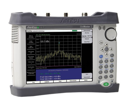
Some of that diversified portable measurement capability is evident in the Anritsu S362E Site Master™ Compact Handheld Antenna and Cable Analyzer. It packs what was once a complete test bench into a portable unit that weighs about 6 lbs. with a bright 8.4-in. color touchscreen display. It includes a 2-MHz-to-6-GHz antenna and cable analyzer, a 100-kHz-to-6-GHz spectrum analyzer, a 50-MHz-to-6-GHz power meter with ±0.16-dB accuracy, a GPS receiver for location stamping of test sites, and even a bias tee and power supply capable of as much as +32 VDC for powering active devices during testing. The model S362E analyzer is capable of one-port phase measurements and two-port loss measurements on antenna/cable assemblies using FDR techniques. It can also apply an inverse Fourier transform function to convert FDR measurements to TDR data for determining the distance to fault of lossy sections in cable assemblies.
When the need is for testing antennas and cables at higher frequencies, the Anritsu S820E Cable & Antenna Analyzer reaches 40 GHz with its model. It is available with many frequency options, from 1 MHz to 8, 14, 20, 30, or 40 GHz, all with 100-dB or better dynamic range, and runs for 6 hours on a rechargeable lithium-ion battery. The portable, handheld analyzer includes a GPS receiver and vector voltmeter, with options for a vector network analyzer (VNA) and microwave power meter (which requires an additional, external USB power sensor). The compact analyzer weighs just 6.6 lbs. (3 kg) with performance that belies its small size, making one-port loss measurements and two-port transmission (magnitude and phase) measurements with outstanding temperature stability of ±0.02 dB/°C and ±0.3 deg/°C. Frequency accuracy is ±1 ppm with 1-Hz frequency measurement resolution. Versions operating to 14 GHz use Type N connectors; higher-frequency versions use K connectors.
For higher-frequency signal and spectrum analysis, the Keysight N9918B FieldFox portable microwave analyzer features a 114-dB dynamic range from 30 kHz to 26.5 GHz for evaluating antennas and their interconnections in terrestrial and satellite communications systems. Even though it is a lightweight, battery-powered portable analyzer, it achieves laboratory-like measurement accuracy of ±0.7 dB from 30 kHz to 10 MHz and ±0.5 dB from 10 MHz to 26.5 GHz. Albeit with less accuracy, the analyzer can be extended to 110 GHz for millimeter-wave measurements using an optional add-on frequency converter.
With slightly higher-frequency nominal starting range, the Keysight N9960A FieldFox handheld microwave spectrum analyzer operates from 5 kHz to 32 GHz with ±0.5-dB measurement accuracy. It has a 103-dB dynamic range and can function as a frequency downconverter with 25-MHz intermediate-frequency (IF) bandwidth for signal and spectrum analysis into the millimeter-wave frequency range with additional equipment. The portable analyzer includes a cable and antenna analyzer (CAT) mode for automated measurements of insertion loss and return loss in cables and their interconnections.
The N9960A analyzer is fortified by many options, including the choice of a built-in power meter, GPS receiver, and/or +32-VDC bias source. An additional option provides an inverse Fourier transform to convert FDR measurements to TDR data for distance-to-fault measurements. For maintaining and measuring radar systems, the analyzer can be equipped with wideband pulsed measurement capability (which can be extended into the millimeter-wave range with the downconverter capability) to quickly determine essential pulse signal parameters, including rise time, fall time, and pulse width. Additional calibration kits enable measurements on interconnections with different connector types, including Type N connectors at 50 ? and at 75 ? as used in cable-television (CATV) installations.
For on-site cable testing based on TDR measurements, the MOHR CT100B series of portable cable analyzers can find faults spaced less than 1 cm apart with better than 1% accuracy. The battery-powered cable testers perform TDR measurements with 16-b resolution, providing enough memory to save data for thousands of measurements for perming measurements at multiple test sites. The analyzers can convert TDR data to scattering (S) parameter data, including S21 for insertion loss and S11 for return loss for analysis, to supplement analysis in commercial software programs. The units include several computer interfaces, including USB and 10/100-Mb Ethernet, to connect them to external computers. Impedance matching adapters, such as 50 to 75 ?, 50 to 93 ?, and 50 to 125 ?, are available as options when working on non-50-? systems.
Mechanical precision is an important attribute of many antenna systems and the Sunsight AAT-15 AntennAlign Alignment Tool (AAT) evaluates the mounting accuracy and positional consistency over time to determine of a satcom ground-station antenna is properly positioned for optimum system performance. The AAT-15 can be mounted in several ways to fit different antenna configurations for checking on their mounting accuracy. The unit is added to a ground-station or other antenna type upon installation and the antenna’s initial coordinates are stored in the AAT-15 as a reference. The unit then employs built-in accelerometers, laser range finders, and a pair of GPS receivers to measure antenna azimuth accuracy within ±0.3 deg. of its initial positioning and tilt accuracy within ±0.25 deg. Antenna height can be measured over a range of 0.3 to 1000 m.
Antennas link to receivers and transmitters in many electronic systems by means of coaxial cables and testing them together provides a more complete picture of how they work together in a system. While no single test equipment can perform all the measurements needed to check antenna/cable assemblies for optimum performance, the analyzers and testers reviewed here represent a few examples of the measurement solutions from Axiom Test Equipment, with additional information on any unit available at any time from www.axiomtest.com.
Back to BLOG