

Tracking Testers for Radars and Communications Systems
December 02, 2022
 |
Communications links and radars are among the most widely used electronic systems, and for most markets, whether military or commercial, industrial or medical. Both systems can make a difference between life and death, whether on a battlefield, in a home, or on a highway, although functioning in much separate ways. Communications systems transfer information between locations while radars search for targets. Their functions are made possible by diverse types of electromagnetic (EM) waveforms and, as a result, test equipment that is optimum for one type of system may not be as well suited for the other type of system. A quick review of the essential differences between communications and radar systems can help target the types of test equipment with the capabilities needed to optimize the performance of each type of electronic system.
Communications systems function by modulating a continuous-wave (CW) carrier signal, by varying a signal characteristic to create amplitude modulation (AM), frequency modulation (FM), or phase modulation (PM). A communications channel consists of a transmitter sending a modulated signal by a direct-path route or via reflections from obstructions such as buildings to a receiver. Two-way communications are possible with a transmitter and receiver (or transceiver) at both ends of the communications channel. Networked communications ties multiple users back and forth through some form of switching transceiver station, such as a base station in a wireless cellular network.
Radar systems can operate with CW signals as well as with short-duration pulses. In contrast to a communications system in which low-power signals are sent from a transmitter to a remote receiver, a radar system transmits higher-power signals back to itself, after bouncing them off some form of target, which may be moving or in a fixed location. Changes that have occurred in the signal characteristics from the time it is transmitted to the time it is received provide details about a target that has been “illuminated” by the EM beam, such as its distance from the radar transmitter. In a communications channel, the channel characteristics such as noise and interference provide unwanted degradation of the system’s performance and it is signal characteristics such as phase noise and harmonics that can be minimized in a test signal for those systems. A radar, on the other hand, studies the channel characteristics to gain knowledge of an illuminated target. Radar systems typically require higher transmit power levels than communications systems, especially when attempting to detect a small target surrounded by larger obstructions. Smaller targets have less surface area than larger targets so that more transmit power is needed to produce usable return signals.
Evaluating a communications system or a radar system requires a means of producing test signals that are like those used by the system as well as some means of receiving and analyzing signals from a system and/or its components and devices to duplicate how transmitted signals appear to the system. The types of signals used in communications and radar systems are as diverse as the types of systems themselves. Communications systems range from short-range wireless Bluetooth links, such as between a computer and printer, and more complex 5G wireless networks with billions of users worldwide. Radars are now used in all markets, from automotive safety to weather forecasting, with signals covering a wide range of power levels as well as waveform configurations, from CW signals to extremely short pulses. Testing a communications system requires the capability to generate and analyze signals with the type of modulation used in the system under test as well as its components, such as active and passive antennas. Testing a radar system and its components calls for the capabilities to generate and analyze a wide range of pulsed signal formats at suitable power levels. Radar systems can be active, in which they generate their own signals for transmission, or passive, where outside signals, such as from cellular towers or broadcast stations, are acquired and redirected to illuminate a target. Testing both types of radars require knowledge of the transmitted signals to duplicate them for measurement purposes.
Modern test signal sources often have built-in test software or can be supported by external test software to produce the various modulation formats used in communications systems, such as quadrature amplitude modulation (QAM) and quadrature phase shift keying (QPSK) modulation. The test software may also enable automated communications system-level measurements, such as adjacent-channel power ratio (ACPR) or even measurements on key components, such as amplifiers, which help describe overall system behavior with complex modulated signals, including error vector magnitude (EVM) measurements. Test signal sources for radars must provide the combination of wide bandwidth and pulse control to generate the type of pulse train needed for checking a radar system under test. Shorter pulses require wider bandwidths but provide more detailed resolution of a target than longer pulses. Shorter pulses contain less EM energy than longer pulses and so must be transmitted at higher power levels to produce usable radar return signals.
In many cases when creating radar transmit signals, a test amplifier will be part of the test setup to boost the test signal output power to a desired level. The test signal source should be capable of providing the input power required by the test amplifier for optimum amplifier performance. Some radar systems, such as ultrawideband (UWB) radars, operate with extremely narrow pulse widths of 1 ns or less to minimize interference with other electronic systems. Testing such a radar requires a test source capable of such narrow pulses and an analyzer capable of detecting them. Pulsed signals are defined by their many characteristics. In addition to pulse width, which is the time the pulse spends at its maximum amplitude, there is the risetime or time required for the voltage of a pulse train to move from a baseline or zero level to the peak amplitude and the fall time, the time for the pulse to return from the peak amplitude back to the baseline level. A pulse train consists of many pulses in sequence, at a defined pulse repetition interval (PRI) or pulse repetition frequency (PRF).
Targeting Test Gear
Ideal signal sources for testing communications and radar equipment should combine high performance with versatility. Radar systems with moving target indication (MTI) capability, for example, identify a moving target by using pulses with controlled delay times to remove the clutter formed by return signals from stationary objects surrounding the moving target. Evaluating this type of radar requires a test signal source capable of producing suitable pulses but also of precisely adjusting the delay times between pulses.
Digital technology has enabled the development of versatile signal sources and analyzers with high performance, capable of generating and scrutinizing the complex waveforms that power modern communications and radar systems. As an example, the Keysight M8190A arbitrary waveform generator is not just a signal generator but what the company refers to as a signal scenario generator (SSG) capable of applying high-speed digital signal processing to produce complex modulated signals. Designed in a modular AXIe format, it can be used with an additional module to align as many as 12 test signal channels with 14-b resolution to 8 GSamples/s and 12-b resolution to 12 GSamples/s (different options). It is flexible, allowing sample rates to be varied from 125 MSamples/s to 8 or 12 GSamples/s, but it also has the performance, with an analog bandwidth of 5 GHz to support generation of narrow pulses. Output signals are available in single-ended or differential formats at SMA connectors.
The digital architecture features fast response times, with less than 15 ps typical jitter and 20-to-80% and 80-to-20-% rise/fall times as sharp as 60 ps. When pulses must be delayed, as in the generation of signals for testing MTI radars, the M8190A provides a delay range of 0 to 10 ns with resolution of 50 ps or better. Communications modulations and pulse formats can be created and downloaded with the aid of waveform generation software such as Signal Studio Pulse Builder, SystemVue, MATLAB, and LabView. For sensitive or even classified tasks, as much as 2 GSamples/channel arbitrary waveform memory is erased when power to the arbitrary waveform generator is turned off. In addition to its own 5-GHz pulsed outputs, the M8190A can be used with a PSG signal generator from Keysight Technologies as a frequency upconverter to produce modulated and pulsed signals as high as 60 GHz for millimeter-wave (mmWave) testing.
For higher-frequency test signals, the Rohde & Schwarz SMA100B is available with frequency coverage as broad as 8 kHz to 67 GHz (with options), with a base configuration running from 8 kHz to 20 GHz. The signal generator is well equipped with modulation capabilities, including AM, FM, PM, and pulse modulation, and is characterized by excellent spectral purity, with typical single-sideband (SSB) phase noise of -119 dBc/Hz offset 20 kHz from a 10-GHz carrier. Even the phase noise performance has an option, with a SSB level of -132 dBc/Hz offset 10 kHz from a 10-GHz carrier available as an option for phase-sensitive communications and radar signal generation. Pulse modulation includes 10-to-90% risetime of better than 10 ns, PRFs of 0 Hz to 25 MHz, and pulse widths less than 20 ns.
A digital architecture based on high-speed digital-to-analog converter (DAC) operating at rates from 1.5 kSamples/s to 25 GSamples/s contributes to the performance and flexibility of the Tektronix AWG70002A arbitrary waveform generator. The two-channel test sources can produce communications signals with complex modulation and long-running pulse sequencies by merit of as much as 8 GSamples waveform memory per channel. With an analog bandwidth of 13.5 GHz, the signal source operates to 50 GSamples/s with 10-b resolution and generates wideband signals to 10 GHz at typical levels from -8 to -2 dBm. Pulses can be generated with typical 20-to-80% rise times of 22 ps. Signals feature low wideband noise, with typical spurious-free dynamic range of -80 dBc. Armed with the company’s RFXpress software, an operator can program complex modulation and pulse formats, including Barker codes and linear frequency modulation (LFM).
When analyzing communications signals, the test receiver, such as an oscilloscope, signal analyzer, or spectrum analyzer, must be capable of processing test signals with the modulation format of interest. For analyzing radar signals, the test receiver must duplicate the functionality of the radar receiver being evaluated in terms of providing required pulse characteristics such as rise and fall time. For example, the Keysight DSOS604A digital oscilloscope, a member of the company’s Infinium 9000 Series oscilloscopes, features maximum analog bandwidth of 6 GHz. It provides sampling rates of 10 GSamples/s for four channels and 20 GSamples/s for two channels. For studying high-speed pulses, it has a 10-to-90% risetime of 85 ps and a 20-to-80% risetime of 59 ps. For an impedance of 50, the sensitivity ranges from 1 mV/div to 1 V/div with bandwidth set from 500 MHz to 4 GHz in 500 MHz increments. Test results are shown on a 15-in. XGA touchscreen display.
Also with four input channels, the Tektronix CSA7404B Communications Signal Analyzer offers a 4 GHz analog bandwidth and 20 GSamples/s maximum sample rate for analysis of wideband modulated signals. It has 8-b vertical resolution and includes compliance masks for testing wired, wireless, and optical communications systems and their signals at rates to 2.5 Gb/s according to established standards. For radar testing, the analyzer has minimum 20-to-80% rise time of 72 ps and minimum 10-to-90% risetime of 100 ps (with similar fall times).
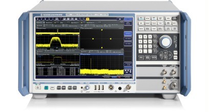
When analyzer noise levels must be kept to a minimum, the Rohde & Schwarz FSW13 Signal and Spectrum Analyzer provides a wide dynamic range for studying both communications signals and radar pulses. With a standard analysis bandwidth of 10 MHz, it can show signals as high as +30 dBm (1 W) and set the reference level as low as -130 dBm, with additional noise suppression from built-in channel and EMI filters. It has a DC-coupled frequency range of 2 Hz to 13.6 GHz and AC-coupled range from 10 MHz to 13.6 GHz, with remarkable 0.01-Hz resolution and 1-Hz marker resolution on frequency readouts. When teamed with a vector signal generator (VSG), the low-noise analyzer provides the setup needed for evaluating communications channels for EVM performance.
For any help in selecting the right assortment of units, please contact the Axiom Test Equipment’s sales department at sales@axiomtest.com, or by calling an Axiom sales representative at 760-806-6600.
Back to BLOG